Terrain Overview
This page introduces the terrain-specific concepts of the Tinman 3D SDK and provides an overview of the related APIs.
Datasets
One of the first building blocks that is encountered when starting to use the Tinman 3D SDK is the terrain dataset, for example the ones listed on the Geodata Examples page.
Terrain datasets are plain files and come in two flavours:
When dealing with terrain data, there is usually some concept of a zoom-level, which indicates the resolution of the data, often given in metres per pixel. For example, BingMaps defines zoom levels from 1 to 19.
| The binary file format of dataset files has been designed so that they may be put on a web server, for being streamed with HTTP/1.1 Range Requests. Please refer to Streaming and Caching for details. |
The Tinman 3D SDK uses the term ground sample distance (GSD) to measure resolution, where the distance is computed in the geocentric frame at ground-level (i.e. ellipsoid height of zero), for neighbouring samples or pixel centers.
In a dataset, the GSD will almost never be constant. However, by using a suitable map projection for the region of interest, the GSD range can be minimized. Since datasets may be associated with arbitrary geo-references, it is impossible to define a fixed set of zoom-levels here.
Instead, geo-referenced cubemap datasets are used, which are based on a custom Gnomonic projection for each cubemap face. A table of standard resolutions is given below.
There are helpers that compute optimal dataset dimensions, for a given geo-reference:
| The Map Coordinates GUI component also shows the GSD at the current cursor location. |
Resolution
Here is a list of standard resolutions for Earth, Mars and Moon, when using geo-referenced cubemap datasets.
Dataset Size 2N (pyramid) |
Ground Sample Distance |
||
|---|---|---|---|
Earth |
Mars |
Moon |
|
8 |
35.12 km |
18.72 km |
9.598 km |
9 |
17.56 km |
9.362 km |
4.799 km |
10 |
8.779 km |
4.681 km |
2.399 km |
11 |
4.39 km |
2.341 km |
1.2 km |
12 |
2.195 km |
1.17 km |
599.9 m |
13 |
1.097 km |
585.1 m |
299.9 m |
14 |
548.7 m |
292.6 m |
150 m |
15 |
274.3 m |
146.3 m |
74.98 m |
16 |
137.2 m |
73.14 m |
37.49 m |
17 |
68.59 m |
36.57 m |
18.75 m |
18 |
34.29 m |
18.29 m |
9.37 m |
19 |
17.15 m |
9.14 m |
4.69 m |
20 |
8.57 m |
4.57 m |
2.34 m |
21 |
4.29 m |
2.29 m |
1.17 m |
22 |
2.14 m |
1.14 m |
58.6 cm |
23 |
1.07 m |
57.1 cm |
29.3 cm |
24 |
53.6 cm |
28.6 cm |
14.6 cm |
25 |
26.8 cm |
14.3 cm |
7.3 cm |
26 |
13.4 cm |
7.1 cm |
3.7 cm |
27 |
6.7 cm |
3.6 cm |
1.8 cm |
28 |
3.3 cm |
1.8 cm |
0.9 cm |
29 |
1.7 cm |
0.9 cm |
0.5 cm |
30 |
0.8 cm |
0.4 cm |
0.2 cm |
Terrain Data
This section explains the primary sources for terrain data: sample rasters and tile pyramids.
Raster
A raster is a regular grid of samples, where each sample holds a number of values, one for each of the data layers:
- Coverage
-
The sample coverage (0 = no data is present, 1 = data is present), that the other sample values are pre-multiplied with
- Displacement
-
Vertical offset from terrain surface along the normal-vector
- Elevation
-
Vertical offset from terrain base geometry along the up-vector
- Material
-
A token of up to 4 weighted materials, out of a palette of 256 materials
- Texture
-
A color value with a red, green, blue and alpha channel
Rasters are represented by the IHeightmap interface.
| For details on how to use raster data, please refer to Geodata Processing. |
The inherent pixel coverage semantic of rasters is pixel-is-point, but a IHeightmap may optionally use pixel-is-area, for example when wrapping a geo-referenced image during geodata processing.
Rasters always have a size of 2N+1 by 2N+1 samples, where 8 ≤ N ≤ 30.
Rectangular rasters are represented with the smallest fitting square raster, using zero coverage for all samples outside of the data rectangle.
Cubemap rasters are built from six individual rasters (one for each cubemap face), where the corner samples are shared by three rasters and the edge samples are shared by two rasters.
| Traditionally, when speaking of heightmaps, there is only an elevation data layer, which initially led to the name of the IHeightmap interface. The concept has evolved, but the name still remains. |
Rasters may be tied to a geo-reference, so that each sample can be mapped to a geo-location, usually on Earth.

When increasing the size of a raster (N+1), new samples (red) may be interpolated from the existing samples (white), for example by using Catmull-Rom splines.
When decreasing the size of a raster (N-1), all odd rows and columns are deleted.
These transformations are applied dynamically at runtime, when consuming raster data for terrain rendering.
| The details of raster management are hidden behind the API, so the following explanations are informational. |
Storage
Storing raster samples in linear storage using row-major / column-major order is only feasible for small sizes (N ≤ 14). To allow greater sizes in conjunction with efficient handling of sparse data, a partitioning scheme is used that groups samples into blocks, which are then stored as binary objects in an embedded database (blocks with zero coverage are not present in the database).
The following figure shows an example partitioning scheme for a 16x16 grid, using a block size of 4x4:
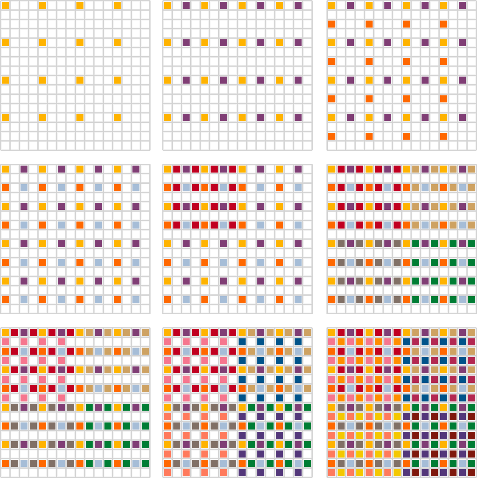
When moving through the figure from left to right, top to bottom, the following blocks are introduced at each step:
-
1st row
-
Block #0
-
Block #1
-
Block #2
-
-
2nd row
-
Block #3
-
Block #4
-
Blocks #5…7
-
-
3rd row
-
Block #8
-
Blocks #9…11
-
Blocks #12…15
-
This partitioning scheme aligns nicely with the hierarchical level-of-detail traversal pattern of right-triangulated irregular nets, which are used to render 3D terrains in realtime.
Pyramid
Pyramid data is basically a tree of equally sized square image tiles, often referred to as tiled maps.
| For details on how to use pyramid data, please refer to Geodata Processing. |
Well-known examples are BingMaps, GoogleMaps and OpenStreetMaps.
The idea is to start with a single image tile that covers the region of interest. For web maps this is usually the Earth in Pseudo-Mercator projection. Then, the root tile is split evenly into four sub-tiles, which quadruples the number of pixels that cover the region of interest, which effectively halves the resolution (metres per pixel).
Tile splitting is repeated until the region of interest is represented with the desired resolution. The resulting tile tree is not necessarily balanced, usually different resolutions are desirable for different regions, for example low resolution for oceans, medium resolution for rural regions and high resolution for urban regions.
The inherent pixel coverage semantic of pyramids is pixel-is-area.
The bottom-most level of a pyramid always has a size of 2N by 2N pixels, where 0 ≤ N ≤ 30. The number of pyramid levels is a function of this full size and the tile size:
levels = log2(full-size / tile-size) + 1
Cubemap pyramids are built from six individual pyramids (one for each cubemap face), where the corner and edge pixels of adjacent faces touch, but are not shared, as it is the case with rasters.
Pyramids may be tied to a geo-reference, so that each pixel center can be mapped to a geo-location, usually on Earth.
The following figure shows an example pyramid with 3 levels, a tile size of 4 and a full size of 16:

The Tinman 3D SDK provides two types of pyramid data: pixel pyramids and texel pyramids. Pixel pyramids provide the source image data for terrain rendering. At runtime, pixel pyramid data may be consumed in flexible ways, for example scaling, slicing, combining or reprojection. As the last processing step, pixel data may be encoded into a GPU-ready texture format, such as BC3, which yields the texel pyramid.
Regarding GPU-based 3D terrain rendering, tiled maps have an inherent problem with texture filtering at tile borders, which is not present when doing typical 2D rendering (web maps, for example). Given a perspective 3D view on a terrain, the GPU will perform anisotropic texture filtering on the texture tiles. At the tile border, the filter kernel is clamped (when using one texture per tile) or bleeds into adjacent tiles (when using a texture atlas), which results in visually apparent artefacts.
To avoid these visual artefacts, pyramids may use padding, which resamples each tile so that a defined amount of pixel data of neighbouring tiles appears within the tile. Then, texture coordinates are adjusted at runtime. There is a one-time computational overhead per tile on the CPU side, which can easily be remedied by using standard caching. There is no overhead on the GPU side.
Overlay
Raster and pyramid data is fed into a processing pipeline which ultimately produces the resources that are required for 3D rendering, such as triangle meshes and textures. Processing is usually distributed between pre-processing and on-the-fly processing at runtime, depending on the needs of the application.
Raster data as well as pyramid data is allowed to be mutable. When the data is modified, the processing pipeline runs incrementally and produces updated 3D resources. This process is quick and may be used interactively at runtime, for example to put surface decal imagery onto the terrain.
Using mutable raster and pyramid data is not suitable for highly dynamic data, such as:
-
Animated terrain decals that move / scale / rotate, for example editing or selection cursors
-
Terrain decals with dynamic per-frame content, such as time-series data or realtime-generated data
In these cases, dynamic terrain overlays may be used:
A dynamic overlay is basically a GPU texture that is rendered on top of the terrain mesh, re-using the existing 3D geometry. The content may be sourced from images or produced at runtime, for example by using GPU render targets.
The APIs provide different methods for putting dynamic overlays onto the terrain surface. For details, please refer to Surface Decals.
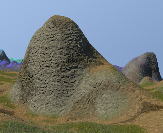
Displacement
Using elevation raster data to create terrains has several limitations, for example:
-
It is impossible to define terrain overhangs.
-
It is difficult to define near-vertical terrain features.
To overcome these limitations, the Tinman 3D SDK allows to use displacement raster data, in addition to elevation data.
|
|
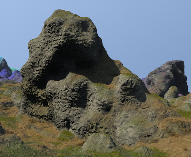
Displacement information that has been fetched from raster data is built into the 3D geometry of the terrain mesh and may be consumed by the application, for example by picking or planting geometry.
Material-based texturing uses GPU tessellation to apply a second layer of displacement, for close-up views at ground level.
|
|
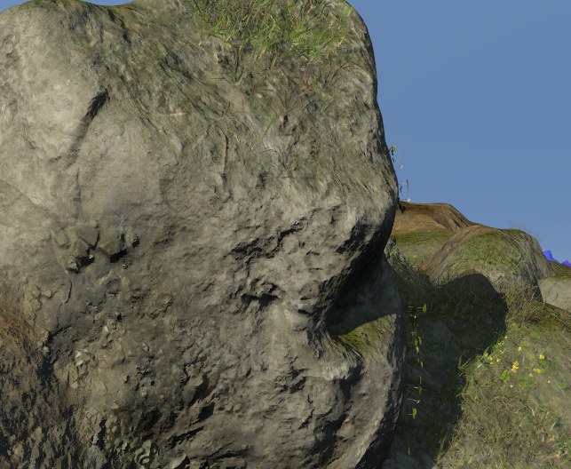
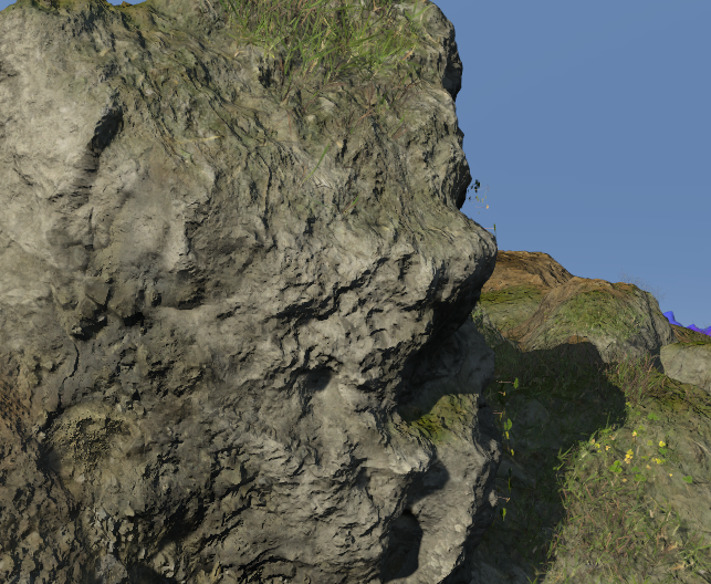
Displacement information that has been sourced from GPU textures cannot be consumed by the application, unless data is read back from the GPU.
Procedural
- IScalarFunction
-
Produces smooth pseudo-random scalar values, for example to generate elevation or displacement via HeightmapBuilder.Procedural.
- IVectorFunction
-
Produces smooth pseudo-random 3D vectors, for example to perform custom mesh modification via IMeshModifier.
- IColorFunction
-
Produces smooth pseudo-random color values, for example to generate texture via HeightmapBuilder.Procedural.
| For details on how to use pyramid data, please refer to Geodata Processing. |
Terrain Mesh
The terrain mesh is made of 3D geometry and zero or more texture layers. The 3D geometry is build from a single raster (i.e. a single IHeightmap object) and each texture layer is built from texel pyramids (i.e. one or more ITexelPyramid objects per layer). Usually, these objects represent the end nodes of a processing pipeline that involves multiple dataset sources and conversions.
| This section describes the concepts behind low-level terrain management, which are important if you are planning to use the Low-level Terrain API. For the other APIs, this section may be seen as informational. |

A naive way to create 3D geometry for a raster is to create a vertex for each raster sample and then triangulate the vertices to form graphics primitives (e.g. triangle strips or triangle lists). By arranging the primitives in a quadtree, rendering selected terrain parts using a pyramid tile of a texture layer is trivial. Obviously, this approach is only applicable to very small rasters.

A common approach to build 3D geometry for large rasters is to use Triangulated Irregular Nets (TINs), where a specific criterion is defined (for example, the spatial error that would be introduced when the raster sample is not included) that determines which raster samples shall be included in the triangulation. Vertices are generated only for included raster samples. The steps for triangulation and quadtree-based texturing then become significantly more complex.

When building a triangulation for a vertex soup that is based on raster samples, special care must be taken to avoid gaps and T-junctions. Gaps are actual holes in the triangle mesh, resulting from misaligned triangle edges, which typically occur between different levels-of-detail. T-junctions produce visual artefacts, although the triangle edges are aligned mathematically, due to floating-point arithmetics applied during rendering.

In a consistent terrain mesh, all gaps and T-junctions have been resolved by splitting the offending triangles. Performing forced triangle splits efficiently is not a trivial task and requires consideration. A popular workaround is to generate additional geometry that simply occludes gaps and T-junctions. This is feasible for visual rendering but will quickly become a problem when using terrain meshes for spatial queries such as picking or collision detection.
CLOD / Quadtree
The Tinman 3D SDK builds terrain meshes that classify as Right-triangulated Irregular Nets (RTINs). An RTIN is a TIN that contains only right-isosceles triangles.
Starting with two root triangles (which form a so called diamond) per cubemap face, triangles are split recursively along their longest edge. This is commonly referred to as longest-edge bisection.
By splitting triangles according to a view-dependent visibility criterion (for example, the screen pixel error that would be introduced by not splitting the triangle), the terrain mesh exhibits continuous level-of-detail, capturing near and far parts of the terrain equally well.

Splitting a triangle introduces a T-junction (see the red vertex with the white border in the figure above), unless its longest edge lies on the border of a rectangular mesh. To resolve the T-junction, a forced split must be performed on the adjacent triangle once (if it has the same size) or twice (if it is bigger). The forced split may trigger another forced split, which creates a chain of recursion that may lead up to the root triangles.
Terrain meshes using RTIN / CLOD have certain advantageous properties for realtime rendering:
-
The midpoint of the longest edge of each non-leaf triangle maps exactly to a raster sample.
-
The access pattern of CLOD is well-aligned with the partitioning scheme of raster datasets.
-
The root diamond represents the root tile of a pyramid.
-
Splitting the triangles of a diamond twice creates four triangle pairs, where each one represents a sub-tile in the quadtree hierarchy of the pyramid.
For cubemap terrain meshes, six RTINs are used, one for each cubemap face.The data structures are built in a way so that all forced triangle splits seamlessly propagate to adjacent faces, without requiring any additional logic.
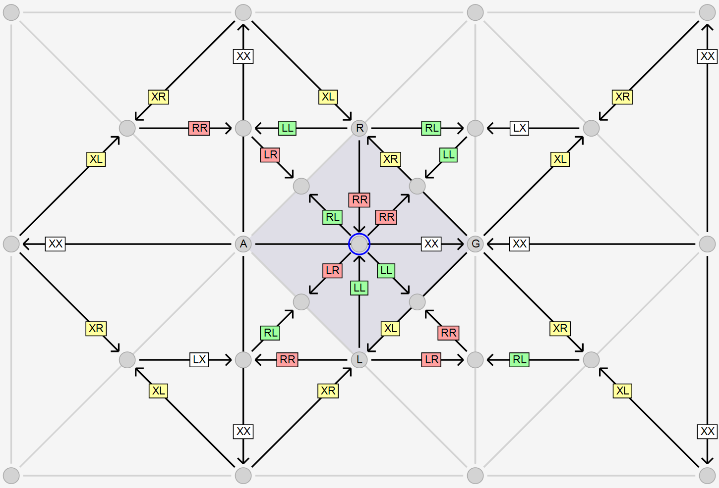
In the figure above, when treating the ARGL as the root diamond of a cubemap face, forced splits (i.e. following LL, LR, RL, RR for the center vertex with the blue border) propagate to the root diamond of the adjacent cubemap face.
| The Low-level Terrain API provides the Rtin class, which may be used to leverage the algorithms and data structures of the Tinman 3D SDK for using CLOD / RTIN meshes, for other use-cases than rendering. |
Spatial Hierarchy
For each terrain mesh, certain hierarchical data structures are maintained, which are intended to speed up spatial queries.
The data structure that is used to represent the CLOD mesh inherently captures the triangle hierarchy that results from longest-edge bisection as well as the quadtree hierarchy of pyramid tiles. Moving through the mesh structure and switching between mesh elements (i.e. vertices, pyramid tiles, triangles) is very efficient.

Aligned with the quadtree of pyramid tiles, the following hierarchy of spatial data is maintained:
- Bounding Sphere
-
The center of the bounding sphere is always the center vertex of the pyramid tile. The radius of the bounding sphere is chosen so that it has the smallest possible value for which the bounding sphere contains all vertices of the raster samples that lie within the area of the pyramid tile. The nested bounding sphere hierarchy is used to accelerate spatial queries.
- Coverage Flags
-
The coverage flags NotEmpty and NotSolid describe the distribution of raster sample coverage values within the area of a pyramid tile, which allows to detect whether an area is fully empty, fully solid or partially empty/solid. The nested coverage flag hierarchy is used for coverage culling, which removes geometry for making holes in the terrain.
- Displacement Range
-
The displacement range captures the minimum and maximum displacement values of all raster samples that lie within the area of a pyramid tile. The nested displacement range hierarchy is used by horizon culling to compensate for possible terrain overhangs.
- Elevation Range
-
The elevation range captures the minimum and maximum elevation values of all raster samples that lie within the area of a pyramid tile. The nested elevation range hierarchy is used by horizon culling to construct the visible horizon at the current viewpoint.
- Material Mask
-
The material mask holds a separate bit flag for the material IDs, which indicates whether the material is present at any raster sample within the area of the pyramid tile. The nested material mask hierarchy is used for material-based rendering and planting.
- Material Range
-
The material range holds the minimum and maximum material weight as well as the maximum material weight sum of the material tokens of all raster samples within the area of the pyramid tile. The nested material range hierarchy is used by planting.
- Version
-
Each time the terrain is modified (for example by painting on it), the terrain data version counter is incremented. Each vertex has its own version counter, which indicates the most recent terrain modification that has affected it. The nested terrain version hierarchy is used to invalidate data that has been computed based on an outdated version of the terrain mesh.
Data Flow
For realtime 3D terrain rendering, terrain data is kept in various memory buffers and is processed by different CPU threads and the GPU. This section introduces the data buffers and explains the overall data flow. For additional details, please refer to Low-level Terrain API.
- Mesh Buffer - CPU
-
The mesh buffer acts as a pool of vertices with a fixed capacity. Vertices are taken from this pool to build CLOD terrain meshes. Deleted vertices are returned to the pool and may be re-used later. Both vertex data and mesh structure data is stored in the mesh buffer.
- Shadow Buffer - CPU
-
The shadow buffer represents a snapshot of the mesh structure data in the mesh buffer. Snapshots are used to implement consistency when accessing the contents of the mesh buffer concurrently.
- Vertex Buffer - GPU
-
The vertex buffer stores encoded vertex data, for rendering with the GPU. There is a one-to-one mapping between vertices in the vertex buffer and the vertices in the mesh buffer.
- Structure Buffer - GPU
-
The structure buffer stores mesh structure data, for performing Triangulation with the GPU. There is a one-to-one mapping between vertices in the structure buffer the the vertices in the mesh buffer.
- Texture Buffer - GPU
-
The texture buffer is implemented as a texture atlas which caches texture tiles in one or more 2D textures on the GPU, usually packing multiple tiles into a single texture.
At runtime, several threads are used to access terrain data and to process CLOD terrain meshes:
- Background Tasks
-
A pool of background threads is used to read heightmap and texture data asynchronously.
- Refinement Thread
-
The refinement thread updates the CLOD terrain mesh structure, by adding or removing vertices, based on the defined visibility criterion and the data that has been read by the background tasks. This thread maintains the mesh buffer.
- Render Thread
-
The render thread triggers snapshot creation in the shadow buffer and subsequently operates on it, for example by performing view-frustum culling as preparation for rendering. It submits data uploads to the GPU, sourcing data from the shadowed parts of the mesh buffer, in order to update the vertex, structure and texture buffers on the GPU.
- GPU Threads
-
The GPU threads execute the commands that have been submitted by the render thread, using the shadowed data the has been uploaded to the GPU buffers.
The shadow buffer ensures that the render thread and the GPU threads will never access any data that is being updated by the refinement thread. Also, it ensures that the refinement thread does not delete any data that is still being used by the other threads. This makes it possible to use shared memory buffers and to perform efficient GPU updates.
Triangulation
The triangulation process is responsible for extracting leaf triangles from a CLOD mesh, either for the whole mesh or for specific quadtree tiles. Several triangulation modes exist, to accomodate different use-cases, such as realtime 3D rendering or 3D mesh export.
- TriangleList / TriangleStrip
-
The triangulation result will be a list of independent triangles (3 vertex references per triangle) or a strip of connected triangles (2 initial vertex references plus 1 vertex reference per triangle).
Triangle lists and strips can be consumed by practically all graphics APIs, even legacy ones like OpenGL 1.x or Direct3D 9.
Most file formats for 3D models use triangle lists and/or triangle strips to define geometry.
- TriangleTerminal
-
The triangulation result is a list of terminal triangle codes, which refer to the data structure of the Structure Buffer (~0.25 codes per triangle).
Terminal triangle lists may be consumed by modern graphics APIs like Direct3D 11+ or OpenGL 4.3+, using Compute Shaders.
- SectorList
-
The triangulation result is a list of sector codes, which refer to the data structure of the Structure Buffer (~0.01 codes per triangle).
Sector code lists may be consumed by modern graphics APIs like Direct3D 11+ or OpenGL 4.3+, using Compute Shaders.
Using high-end graphics APIs like Direct3D 12, sector code lists may also be consumed directly with Mesh Shaders.
Traversal
A typical operation on a CLOD mesh performs a top-down traversal of its quadtree while analyzing the spatial hierarchy, in order to optimize performance by skipping irrelevant mesh parts. During traversal, individual quadtree tiles may be flagged as culled or marked, which creates a filtered quadtree. It is possible to have multiple independent filter states of the same quadtree and to copy flags between them.
It is common to chain operations, where the subsequent operation consumes the flags that have been output by the preceding operation. For example: remove invisible terrain parts by adding cull flags in the first operation, then perform texturing of the visible terrain parts by adding mark flags to textured quadtree tiles in the next operation and finally perform triangulation of the marked terrain parts in the last operation, for GPU rendering.
APIs
Different APIs for terrain features are included in the Tinman 3D SDK. The choice which to use depends on the context into which the terrain features are to be integrated.
If a 3D engine already exists, using the Low-level Terrain API provides the greatest amount of flexibility.
If an application already exists, using the High-level Terrain API provides a standard way of adding terrain features.
With the Scene API, new applications or components can be created quickly and easily.
The Data Processing API provides the geodata import and processing features of the Tinman 3D SDK, for integration into applications or content pipeline tools.
Please refer to Tutorial for an overview of the tutorials and examples and how they relate to the various APIs.
Low-level Terrain API
This API provides a set of loosely coupled components, which need to be set up and combined carefully, in order to implement terrain features. While this API provides the greatest amount of flexibility, it also requires considerable effort to get things done.
| The tutorials 10…19 (see below) are designed to provide a run-through of this API. |
For a conceptual overview of this API, please refer to the Terrain Mesh section.
Using this API involves these basic steps:
-
Create a MeshBuffer object, which provides the data storage for zero or more terrain meshes.
-
Create one or more IMeshDynamic objects. Each one represents an independent terrain mesh.
-
Call MeshBuffer.MeshUpdate periodically to synchronize with background refinement of the terrain meshes.
-
Create and use IMeshBound objects, to perform tasks on the terrain snapshot such as culling, texturing or triangulation.
At this level, it may be necessary to use custom components that interface directly with the surrounding application infrastructure, in order to manage and access GPU resources (IVertexBuffer, IIndexBuffer, etc.). If the built-in components are not suitable, you may implement your own components. Please refer to the source code of the following SDK components to find examples on how to implement custom GPU components:
-
DirectX9, DirectX11, DirectX12
-
OpenGL, OpenGLES
-
Vulkan
The following examples and tutorials involve this API:
High-level Terrain API
This API wraps the features of the Low-level Terrain API in a small number of terrain-specific domain classes, which represent the primary concepts of terrain handling, such as the terrain mesh, texture layers and surface decals. With this API, only terrain-specific features are available.
| The tutorials 20…29 (see below) are designed to provide a run-through of this API. |
Using this API involves these basic steps:
-
Create a TerrainBuffer object.
-
Create one or more TerrainMesh objects.
-
Populate the terrain mesh with TerrainDecal, TerrainLayer, TerrainModel and TerrainPlanting objects.
-
Create one or more TerrainView objects and perform the application loop callbacks for each one. The TerrainViewWidget class may be used for this.
This API is built on top of the GPU Rendering abstraction layer and thus uses IGraphicsContext objects for GPU access.
Please refer to the source code of the following SDK components to find examples on how to implement a graphics context:
-
DirectX9, DirectX11, DirectX12
-
OpenGL, OpenGLES
-
Vulkan
The domain classes in this API impose several assumptions and feature decisions, which may not be suitable for all use-cases. If this is the case with your application, you may consider falling back to the Low-level Terrain API or adjusting the source code according to your needs.
The following examples and tutorials involve this API:
Scene API
This API wraps the features of the High-level Terrain API and augments them with a framework for building interactive 3D scenes, using the commonly known scene-graph approach. With this API, many non terrain-specific features become available.
| The tutorials 30…39 (see below) are designed to provide a run-through of this API. |
For details on how to use the Scene API, please refer to Scene Overview page and the How To Do section.
The following examples and tutorials involve this API:
Data Processing API
This API encompasses those features that process geodata or other non-terrain assets, either up-front in a pre-processing step or on-the-fly at runtime. Data processing involves import to Tinman 3D as well as export to other 3rd-party software.
| The tutorials 40…49 (see below) are designed to provide a run-through of this API. |
For details on geodata processing, please refer to the Geodata Examples and the Geodata Processing page.
The following examples and tutorials involve this API:
How To Do
The following section describes how to approach the most common tasks when working with realtime terrains.
For each task, separate explanations are given for the Low-level Terrain API, the High-level Terrain API and the Scene API.
Collision Detection
 This section is not yet available, see roadmap for details.
Geometry Planting
This section explains how to perform automatic planting of geometry on the terrain surface, for example grass, trees, rocks or other objects. Usually, this involves geometry instancing on the GPU side.
Planting is performed adaptively, taking into account the Terrain Data and the current Terrain Mesh structure.
For terrain editing, dynamic planting may be used to provide quick feedback for the given planting options.
For terrain rendering, static planting is favorable: here, planting is performed up-front on static terrain mesh chunks.
Low-level Terrain API
Dynamic planting is performed by the Planting class. The PlantingOptions class provides the options that will control the planting process.
An application is required to provide an IPlanter object, which generates geometry instances, based on the information it receives from the planting process. A VertexBufferCache object is then used to store the data of the generated geometry instances.
Please refer to Tutorial_15_Materials and Tutorial_18_Painting tutorials for more information.
High-level Terrain API
Dynamic terrain planting is configured in two steps:
-
Create TerrainPlanting objects, which define the options and behaviour for planting geometry.
-
Use TerrainMesh.PlantingAdd to add TerrainPlanting object to a terrain.
Please refer to Tutorial_22_Game and Tutorial_26_Bennu for more information.
Scene API
To configure terrain planting in a scene, use IScene.Terrain to obtain the underlying TerrainMesh object and then use the High-level Terrain API.
GPU Rendering
This section shows how the different terrain APIs relate to the GPU Rendering abstraction layer.
| The AddOns components provide ready-to-use implementations for the interfaces mentioned below, which deal with graphics abstraction. |
Low-level Terrain API
This API requires access to GPU buffer and texture resources. These must be provided by client code, in form of instances of the following interfaces:
Creation of GPU contexts and actual rendering is outside of the scope of this API. These tasks must be performed by client code, for example by using the built-in implementations of these interfaces:
High-level Terrain API
When using this API, an instance of IGraphicsContext must be provided by client code, for example by creating one using the built-in IGraphicsContextFactory implementations.
Each TerrainView object must be attached to a graphics context by using the IGraphicsComponent callback interface. GPU rendering is then performed when the IRenderable.Render method is called and GPU resources are managed automatically.
The following IRenderEffect implementations used by this API:
-
IGraphicsEffect (2D drawing)
-
IModelRendererEffect (3D model rendering)
-
IProcessEffect (post-processing effects)
-
IRendererEffect (simple 3D drawing)
-
ISkyEffect (background sky)
-
ITerrainEffect (terrain rendering)
Scene API
Just like with the High-level Terrain API, client code must provide an IGraphicsContext object for each SceneView object by using the IGraphicsComponent callback interface. Then, this API will manage GPU resources, effects and rendering automatically.
To perform GPU rendering, the following callback methods may be used (see Application Loop):
-
ISceneEntityView.Render2D
2D drawing with Graphics -
ISceneEntityView.Render3D
3D drawing with Renderer -
ISceneEntityView.RenderOffscreen
Offscreen rendering to textures and buffers
Mesh Deformation
There are various ways to modify and deform the Terrain Mesh at runtime, which classify as one of the following:
-
Terrain Data modifications that are applied in realtime, for example terrain painting.
-
Terrain Mesh modifications that are computed at runtime, for example procedural detail.
-
GPU Rendering effects, such as Displacement mapping.
Low-level Terrain API
When creating a IMesh object via MeshBuffer.Create, a IHeightmap object must be specified via MeshOptions.Heightmap.
When Terrain Data updates are performed via IHeightmap.UpdateRegion, the IMesh object will receive HeightmapEventArgs notifications via IHeightmap.OnUpdated and the Terrain Mesh will adapt automatically.
Analogously, updating Terrain Data via IPixelPyramid.SetTileData will trigger PyramidEventArgs notification through IPyramidBase.OnUpdated, which tells the TextureAtlas object which texture tiles to invalidate and reload the next time they are needed for Surface Texturing.
With MeshOptions.Modifier, a IMeshModifier object may be specified, which will receive MeshSample values that are based on the actual Terrain Data and may modify them, before they are used to build the Terrain Mesh geometry. The modifier cannot be changed afterwards.
High-level Terrain API
When creating a TerrainMesh, a MeshOptions object must be provided, which may define a IMeshModifier object for the terrain mesh. The modifier cannot be changed afterwards.
When using material-based texturing, GPU displacement mapping may be applied. Use TerrainView.DisplacementScale and TerrainView.DisplacementThreshold to control tessellation and detail.
Scene API
A IMeshModifier object may be specified via SceneOptions.TerrainModifier when creating the scene. The modifier cannot be changed afterwards.
With IScene.Correction, the CorrectionLayer object of the scene may be accessed. By adding 2D vector shapes in form of HeightmapShape objects, the Terrain Data may be adjusted at runtime, for example to level the terrain at airports.
Scene entities may provide ready-to-use terrain manipulations, for example the LevelCorrection scene entity.
Shadow Mapping
The Tinman 3D SDK provides a robust mechanism for performing cascaded shadow mapping for large terrains on a global scale.
Low-level Terrain API
All shadow mapping calculations are performed by the ShadowMapping class. Being a IMeshTraversal, it must be associated with a terrain mesh.
High-level Terrain API
With TerrainView.Shadows, the ShadowMapping object may be accessed, similarly to the Low-level Terrain API.
Use the TerrainView.ShadowTweak property to fine-tune the depth range of the shadow cascades.
Scene API
With ISceneView3D.Terrain, the shadow mapping features of the TerrainView may be accessed, similarly to the High-level Terrain API.
Spatial Queries
The Terrain Mesh provides spatial acceleration data structures on the CPU, which may be used to perform various kinds of spatial queries.
This section explain how the APIs can be used for performed spatial queries.
Low-level Terrain API
At the lowest level, a spatial query is represented by a class that implements the IMeshTraversal interface. To perform the query, an instance must be created and attached to a terrain mesh, via IMeshBound.MeshBind.
The query class uses the MeshTree to traverse through the terrain mesh, accesses the Terrain Data and Spatial Hierarchy information that is stored in a VertexArrays object and performs spatial computations accordingly.
The following built-in query classes are available:
-
DistanceToGround
Computes the smallest omni-directional distance to the terrain surface, for a given point in 3D space. -
HeightAboveGround
Computes the height above the terrain surface, along the up-vector, for a given point in 3D space. -
Picking
Picks a location on the terrain surface by following a ray in 3D space.
High-level Terrain API
This API provides access to ready-to-use spatial query objects, which are owned by a TerrainMesh object:
Scene API
With IScene.Terrain, the spatial query objects of the TerrainMesh may be accessed, similarly to the High-level Terrain API.
Additionally, the Scene API provides a top-level mechanism to perform spatial queries and consume the result query results. Please refer to Spatial Queries for details.
Surface Decals
The geometry of a Terrain Mesh can be reused to render decals onto the terrain surface, without the need to generate additional geometry.
Low-level Terrain API
When performing decaling, this API needs to query information about each surface decal in use. The IDecal interface is used to query this information.
Client code must implement the IDecal interface and pass instances of the implementation class to this API. Such decal objects will typically contain additional information, for example the texture to use for rendering.
One or more Decaling objects must be created and attached to a terrain mesh. Then, decals may be added via Decaling.DecalAdd. During mesh Traversal, zero or more DecalingBatch values are generated.
Using DecalFace.Decal of DecalingBatch.Mapping, client code may retrieve the IDecal object via Decaling.Decals, perform a typecast to a known implementation class and then consume the additional information.
High-level Terrain API
This API provides the TerrainDecal class as an implementation of the low-level IDecal interface.
Using TerrainMesh.DecalAdd, TerrainDecal objects may be added to a terrain.
Scene API
With IScene.Terrain, the decaling features of the TerrainMesh may be accessed, similarly to the High-level Terrain API.
Use the TextureDecal scene entity to place a dynamic decal onto the terrain surface.
Use the ImageDecal scene entity to place a geo-referenced image onto the terrain surface.
Surface Texturing
The Tinman 3D SDK provides two methods for texturing the terrain surface:
-
Unique texturing
-
Material-based texturing
The first method sources texture data from one or more ITexelPyramid objects and performs unique texturing.
The second method uses the Material layer to perform artificial texturing by mixing the specified material textures.
Material-based texturing may be well-suited for close-up views, near the terrain surface. Unique texturing may be a good choice for more distant terrain parts.
Low-level Terrain API
At the lowest level, unique texturing is performed by Texturing objects, which produce TexturingBatch values that must be processed by client code; this usually involves rendering. Each Texturing object sources texture data from a ITexelPyramid, which must be specified via SetTexture.
To process multiple texture layers in a single pass, the MultiBatching class may be used. Based on the output of the Texturing objects, a set of MultiBatch values is generated, which aggregate the separate TexturingBatch values.
Material-based texturing is performed with Chunking objects. The produced ChunkingBatch values represent terrain chunks which contain no more materials than the specified upper limit, which depends on the implementation of the GPU render effect.
High-level Terrain API
To perform unique texturing, use TerrainMesh.LayerCreate to create a TerrainLayer object of type Texture. Then configure texturing using these properties:
-
Use TerrainLayer.Texture to access the TerrainLayerTexture object.
-
Use TerrainLayerTexture.Slot to access the TerrainLayerSlot objects.
-
Use TerrainLayerSlot.Set to specify a texture data source.
-
Use TerrainLayerTexture.Mapping to access the TerrainSlotMapping object.
-
Configure the TerrainSlotMapping object, to map individual texture data channels (red, green, blue, alpha) to actual terrain material values, for example albedo and normal vectors.
These properties may be used to query the current status of unique texturing at runtime:
To perform material-based texturing, use TerrainMesh.LayerMaterial to access the TerrainLayerMaterial object. Then configure texturing using these properties:
-
Create one or more TerrainMaterial objects. Each one defines a terrain material, which may either consist of a single planar texture or separate textures for tri-planar mapping.
-
Use TerrainLayerMaterial.Add to assign terrain materials to a terrain mesh.
-
Set TerrainLayerMaterial.Chunks to a reasonable value.
-
Use TerrainView.LightingSpace to access the TerrainSpace object, in order to control the coefficients of tri-planar texture mapping on curved surfaces.
Scene API
With IScene.Terrain, the texturing features of the TerrainMesh may be accessed, similarly to the High-level Terrain API.
Terrain Painting
This section is not yet available, see roadmap for details.
Terrain Culling
Culling refers to the process of excluding certain parts of the Terrain Mesh from further processing.
Low-level Terrain API
In this API, terrain culling must be performed by creating culling objects, attaching them to a terrain mesh and then performing mesh traversal.
During traversal, terrain mesh sectors will be culled away by adding cull flags to a MeshTreeFilter.
The following culling objects are available:
-
ConeCulling
Culls away terrain parts that are outside of the specified cone. -
CoverageCulling
Culls away terrain parts where terrain data is not present (e.g. holes with zero coverage). -
DistanceCulling
Culls away terrain parts that are farther away from the camera position as the given distance. -
FrustumCulling
Culls away terrain parts that are outside of the terrain view frustum. -
HorizonCulling
Culls away terrain parts that are under the the terrain horizon that is visible from the camera position. -
RangeCulling
Culls away terrain parts based on the configured criterion, which is based on values in the Spatial Hierarchy. -
RegionCulling Culls away terrain parts that do not intersect with a given arbitrary region in 3D space.
High-level Terrain API
With this API, terrain culling is performed automatically by TerrainView objects.
These properties may be used to fine-tune terrain culling:
These terrain view flags may be used to enable/disable specific terrain culling steps:
Scene API
With ISceneView3D.Terrain, the culling properties of the TerrainView may be accessed, similarly to the High-level Terrain API.
Otherwise, terrain culling is managed transparently by the Scene API.