Scene Overview
This page gives an overview of the Scene API of the Tinman 3D SDK.
Introduction
This section gives a brief overview on how to create, populate and run a scene.
Further details are provided by subsequent sections.
Create a Scene
To create a scene, the following steps are required:
-
Create a SceneOptions object.
-
Configure scene properties for caching and terrain data.
-
Call CreateScene to build a Scene object.
-
Create one or more SceneView objects for the scene.
Alternatively, the SceneViewWidget.SceneCreate method may be used to create a scene and a scene view in a single step.
| Scene views may be created and disposed at any time and do not have to be created up-front at initialization time. |
From this point onward, use the IScene and ISceneView interfaces to access the created objects, in order to populate the scene and to interact with it.
| The implementation classes of IScene and ISceneView provide access to the application loop callbacks, which are usually not needed by scene client code. |
To shut down a scene, do this:
-
Dispose all ISceneView objects.
-
Dispose the IScene object.
Populate a Scene
There are several methods for populating a scene with objects, which can be summarized as follows.
| Interface | Containers | Objects | Comment |
|---|---|---|---|
Adds terrain decals and terrain models to the scene at root level or to a scene entity, which may be nested arbitrarily. |
|||
Adds scene entities to the scene at root level or to an arbitrarily nested scene entity. |
|||
Automatically provides a scene entity view for each scene entity in each scene view. |
|||
Manually adds scene entity views that do not have an owning scene entity to specific scene views. |
Decals and Models
To add objects of the High-level Terrain API to a scene, use the ITerrainEntityContainer interface, which is implemented by the IScene itself and by the SceneEntity class. This way, TerrainDecals and TerrainModels may be added.
Scene Entities
Scene entities may be added by using the ISceneEntityContainer interface, which is implemented by the IScene itself and by the SceneEntity class. The latter is the recommended way of grouping scene entities and arranging them in a hierarchy.
Scene Entity Views
There are two ways to add scene entity views to a scene view:
-
Automatic
For each entity in a scene, the ISceneEntity.CreateView method is called once for each scene view, in order to provide an optional scene entity view which represents the scene entity visually. All built-in scene entities make use of this. Client code does not need to deal with that, unless it implements an own ISceneEntity class. -
Manual
For some use-cases, there exists only an ISceneEntityView object, without an owning scene entity (for example, the CompassView). These scene entity views must must be added to scene views manually, by using the ISceneView interface.
Run a Scene
To run a scene, the application loop callbacks must be performed for all SceneView objects, as defined by the IApplication interface.
| Please refer to Example_Application as an example for creating an application that runs a scene. |
These are the required application loop callbacks:
-
IGraphicsComponent.GraphicsAttach
Attach to graphics context -
IInputConsumer
Consume event-based user input -
IUpdateableFrameTime
Update time index -
IGraphicsComponent.GraphicsResize
Apply changed scene view size -
IRenderPreparable
Prepare rendering -
IRenderable
Offscreen and 3D rendering -
IRenderable2D
2D rendering -
IGraphicsComponent.GraphicsDetach
Detach from graphics context
Performing these callbacks is sufficient for running the scene. No other actions are required.
The following callbacks are optional and will provide additional functionality:
-
IProfilerConsumer
Enable output of runtime profiling values -
IInputConsumerEx
Consume state-based user input
An application may choose to perform these callbacks manually, for example when integrating a scene into its own application framework.
The standard way to run a scene is to wrap all scene views up into one or more IApplication objects and then run these applications using the Application framework.
| Use Run.This to run a single application in a single top-level window. |
-
Wrap each ISceneView object in a SceneViewWidget.
-
Wrap the SceneViewWidget objects in one or more IApplications, for example by using the WidgetApplication helper class.
-
For each IApplication object, do one of the following:
-
Create a top-level ApplicationWindow and an ApplicationLoop, which wraps the IApplication object. Then call ApplicationLoop.MainLoop on each of the ApplicationLoop objects repeatedly.
-
Put the IApplication into an IApplicationControl, which will take care of window and application loop management.
-
Code Concepts
This section explains the prominent code concepts in the Scene API.
Application Loop
The Scene API is used to create interactive applications with real-time 2D/3D graphics, where a small number of standard callbacks are used throughout all components to establish the application loop which drives the scene behaviour.
| Scene entities and views may be added or removed by client-code, while being invoked from a standard callback. If necessary, the Scene API will transparently defer such operations, to ensure consistency. |
Input
Event-based user input is provided by calling the IInputConsumer.ConsumeInput method from client code, separately for each SceneView object. This includes keyboard key and mouse button events (press, release, click) as well as mouse movement (cursor, wheel).
With ISceneView.Focused, an arbitrary component may be selected for being provided with an IInputState object, which it may then use to poll the current state of keyboard keys and mouse buttons. Client code must provide the SceneView object with an input state object via the IInputConsumerEx interface.
Client code may use a SceneViewWidget and WidgetApplication objects, which will then perform the necessary callbacks automatically.
Update
The IUpdateableFrameTime callback is used to provide scene components with the current timestamp increment.
Implementations may perform animation, based on the timestamp increment value, or any other update action that needs to be performed periodically.
Render Prepare
After user input has been processed and updates have been performed with the timestamp increment, the IRenderPreparable callback is invoked once, in order to perform preparations for rendering the current frame.
Such preparation may only involve CPU-based work, such as computing coefficients or other values that will be used during GPU rendering. This is intended to increase the parallelism between the CPU and the GPU, when the GPU is still busy working on the last frame while the CPU is already preparing the next one.
Render 2D
Via the IRenderable2D callback, scene components may perform 2D overlay rendering onto their scene view, using the given Graphics object.
| As much non-GPU computations as possible should be performed during IRenderPreparable, so that during this callback, only render calls need to be made. |
Render 3D
Via the ISceneEntityView.Render3D callback, scene components may render simple 3D geometry into their scene view, using the given Renderer object.
| As much non-GPU computations as possible should be performed during IRenderPreparable, so that during this callback, only render calls need to be made. |
Render Offscreen
Via the ISceneEntityView.RenderOffscreen callback, scene components may perform arbitrary GPU work, usually to generate content for render targets, textures and buffers.
| As much non-GPU computations as possible should be performed during IRenderPreparable, so that during this callback, only render calls need to be made. |
Coordinate Systems
The following coordinate system definitions are used for specification of locations and directions. There are several interfaces and classes to perform coordinate conversion between them.
- Dataset Coordinate System (DATA)
-
Cubemap coordinates are used to refer to samples in a dataset, for example a raster dataset or pixel image. Rectangular datasets are represented by fitting them onto the Z- cubemap face. For details on the definition of cubemap coordinates, please refer to the Cubemap class.
Cubemap coordinates are represented with Vec3D or Vec3I values. Cubemap face coordinates are represented with CubemapFaceCoordsD or CubemapFaceCoordsI values.
- Geocentric Coordinate System (GEOC)
-
A geocentric coordinate system uses three-dimensional cartesian coordinates, where the coordinate origin is at the center of the planetary body and the X, Y and Z coordinate axes have well-defined orientations.
Geocentric coordinate systems are represented with Geocentric objects, where geocentric coordinates are usually specified as Vec3D values.
- Geographic Coordinate System (GEOG)
-
A geographic coordinate system uses two-dimensional coordinates - latitude and longitude - to refer to locations on the surface of a planetary body.
Geographic coordinate systems are represented with CoordinateSystem objects, where geographic coordinates are usually specified as LatLon / LatLonHeight or Vec2D / Vec3D values.
Additionally, a third coordinate may be used to specify a vertical offset, relative to the ellipsoid, the gravity model, the digital terrain model or the terrain mesh.
 Figure 1. Vertical coordinate types
 - Projected Coordinate System (PROJ)
-
A projected coordinate system is based on a geographic coordinate system and uses two-dimensional map coordinates - usually referred to as easting and northing, sometimes westing and southing - which are mapped to latitude and longitude using a well-known mathematical map projection model.
Projected coordinate systems are represented with CoordinateSystem objects, where projected map coordinates are usually specified as Vec2D values.
- Local Coordinate System (LOCA)
-
A local coordinate system uses three-dimensional cartesian coordinates to specify locations in some user-defined frame.
Local coordinate systems are established with ITerrainTransform objects. Affine transformations are represented with Mat4D or AffineTransform values. Local coordinates are specified with Vec3D values.
The following table provides an overview of the possible transformations between coordinate systems, including references to the SDK classes that are involved:
| From / To | DATA | GEOC | GEOG | PROJ | LOCA |
|---|---|---|---|---|---|
DATA |
(1) |
(2) |
(3) |
||
GEOC |
(4) |
(5) |
|||
GEOG |
(2) |
(5) |
(6) |
(6) (7) |
|
PROJ |
(3) |
(6) (7) |
(6) |
(8) |
|
LOCA |
(8) |
(9) |
| 1 | Use a IMapProjectionFactory instance to create a IMapProjection object, which can then be used to transform coordinates between dataset coordinate systems (for example, between dataset samples and image pixels). Coordinates may include a vertical component. |
| 2 | Use a IMapTransform object to transform between dataset coordinates (cubemap or rectangular) and geographic coordinates (latitude and longitude, in the horizontal datum of dataset space). |
| 3 | Use a IMapTransform object to transform between dataset coordinates (cubemap or rectangular) to projected map coordinates (easting and northing, in map space). |
| 4 | To transform geocentric coordinates, Mat4D or AffineTransform may be used, for example with Geocentric.Transform. Usually, this step is performed implicitly, for example when using a IDatumTransform to convert between geodetic datums, such as DatumTransform.GeocentricTransform. |
| 5 | Use a Geocentric object to transform between geocentric and geographic coordinates. Geographic coordinates may include a vertical component, such as ellipsoid height, gravity-related height or height above the terrain. |
| 6 | Use a CoordinateSystemTransform object to transform projected map coordinates or geographic coordinates between coordinate systems. This usually involves different map projections or geodetic datums. |
| 7 | Use a ICoordinateTransform object to transform between projected map coordinates and geographic coordinates, within the same base geographic coordinate system. |
| 8 | With IScene.Topocentric, projected coordinate systems can be generated, often for use with IShape and IModel objects. To map the axes and the scale of such a coordinate system to a LocalTransform, use IScene.TopocentricMatrix. |
| 9 | To transform local coordinates, Mat4D or AffineTransform may be used, for example with ITerrainTransform.Transform. |
State Handling
Scene objects expose their configurable state via properties, to allow client-code to control the behaviour. Usually, a scene object is created with a simple constructor, which sets default values for all state properties. Then, the object is added to the scene and the object properties are modified subsequently.
Here is a list of standard properties, which are used by several scene objects:
| Wrapping properties in separate interface is an optional design decision, intended to avoid redundant documentation effort. It is not intended to be a code guideline or best practice. |
To allow efficient processing of state updates and dependent processing work, scene objects apply state changes lazily, at the latest possible time. At any time, client-code may call the ISceneObject.UpdateState method, to trigger application of all pending state changes. The ISceneObject.NeedsUpdateState property may be used to determine whether pending state changes are present or not.
| The SceneObject base class provides some helpers to facilitate dirty state management in subclasses. |
As a rule of thumb, setting state properties frequently will not incur performance penalties, such as redundant computations. Likewise, not calling the ISceneObject.UpdateState method from client-code will not break the Scene API behaviour, as this method is called automatically at appropriate times.
| State handling of Terrain Objects differs from the behaviour that is explained above. |
Since TerrainDecal and TerrainModel objects are part of the High-level Terrain API, they do not provide the state handling mechanism of the ISceneObject interface. In consequence, the Scene API will not automatically detect changes to those objects, which might skip rendering of the next frame, because scene views only render a new frame if there has been a state change.
When using one of the following methods, a state update will be triggered automatically:
After modifying the state of a terrain object that has been added to a scene, a state update must be triggered by calling the following method:
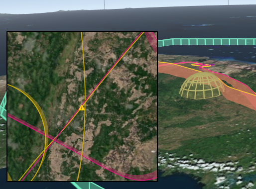
Spatial Queries
A scene contains a global terrain (see IScene.Terrain), terrain objects (see ITerrainEntityContainer), scene entities (see ISceneEntityContainer) and scene entity views (see ISceneEntityView). These objects may contain spatial data, for example 3D models, geo-referenced images, vector shapes or screen overlays.
Client-code may perform spatial queries on a scene, in order to find matching scene objects. Spatial queries are provided by the methods of the ISceneQueryProvider interface, which are implemented by the scene and all scene views:
-
QueryDistance
Evaluates the signed distance field of the scene and returns a float64 value. -
Query
Returns a reusable ISceneQuery object for the given ISceneQueryOp object (for example a ray intersection test). Subsequent query execution yields ISceneQueryResult objects.
These built-in scene query operations are available:
After creation via ISceneQueryProvider.Query, the ISpatialQuery object represents the spatial query. At this point, no computations have been performed. The query object merely carries the information that is required to execute the spatial query subsequently.
These built-in scene objects produce query results:
| A query operation may expose a configurable parameter by implementing the ISceneQueryOpArg interface. If this is the case, the parameter value may be changed later, in order to produce different results when executing the same ISceneQuery object again. |
The ISceneQuery interface defines methods which can be used to specify additional filters and constraints to be imposed on the query results. Client-code should use these to the greatest possible extend, in order to allow the scene query to be executed with optimal efficiency:
To obtain the results of a spatial query, the following methods may be used:
For consuming ISceneQueryResult objects, the Type property may be used. Alternatively, the ISceneQueryResultVisitor interface may be used with Accept, to apply the visitor pattern.
| Related query results may be grouped in GroupResult objects. |
When implementing own scene objects (i.e. custom implementation classes for ISceneEntity or ISceneEntityView), interoperability with spatial query operations may be added by implementing the following methods:
Custom spatial query operations may be created by implementing the ISceneQueryOp interface.
Building Blocks
This section describes common building blocks that are encountered when using the Scene API.
Screen Labels
Each scene view has a ScreenLabelPlacement helper object (see ISceneView.ScreenLabels) for managing 2D overlay labels that will be rendered on top of the scene view content.
Each screen label has an associated depth value, which is used to correctly handle occlusion between screen labels and rendered 3D geometry. When screen labels intersect, the label at the front (i.e. the one having the smallest depth value) will be rendered normally, whereas the other ones will be tagged as occluded and may be rendered in a different style or hidden.
The current screen label placement is cleared before the RenderPrepare callbacks are made by a scene view. Then, scene view components may add screen labels by using the ScreenLabelPlacement.Add method. Alternatively, one of the SceneEntityView.ScreenLabel helper methods may be used.
The content of a screen label is represented with a IScreenLabel object. The same content object may be used to add different screen labels.
| API | Scripting | Description |
|---|---|---|
- |
Creates a screen label that displays an icon which is represented by a Bitmap resource. |
|
- |
Creates a screen label that displays a text, which may be single-lined or multi-lined. |
|
- |
This is an example for a custom IScreenLabel implementation. |
|
- |
Wraps a IScreenLabel in a visual frame. |
|
- |
Stacks two IScreenLabel objects, either horizontally or vertically. |
A screen label may implement the IScreenLabelContent interface, in order to provide an immediate way to update the label content, independently of the internal object composition structure:
A IScreenLabel object does not receive any Application Loop callbacks by default. The ScreenGizmo component can be used to place a screen label onto the screen, while receiving callbacks. The Gizmo class can be used as a base for implementing such a screen label.
Vector Shapes
In a scene, 2D vector shapes are represented with IShape objects. The default implementation Shape provides methods for constructing shapes.
For additional information, please refer to Software Architecture / 2D Shapes and Geodata Processing / Shape Data.
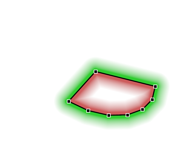
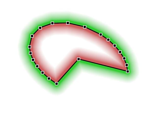
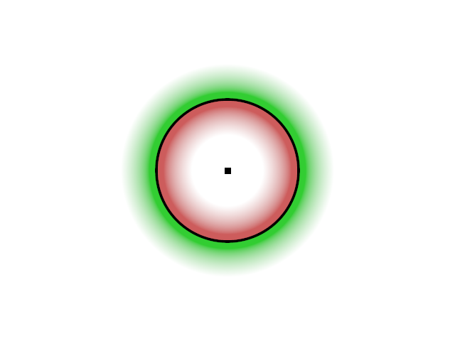
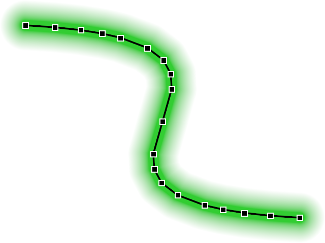
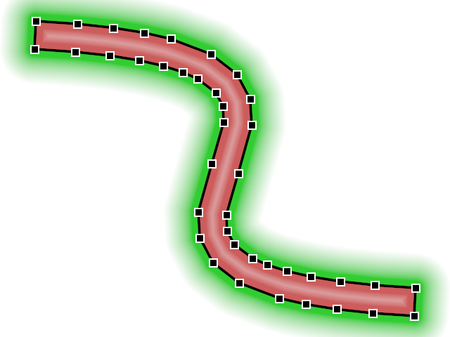
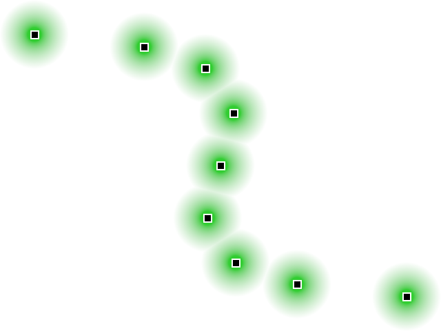
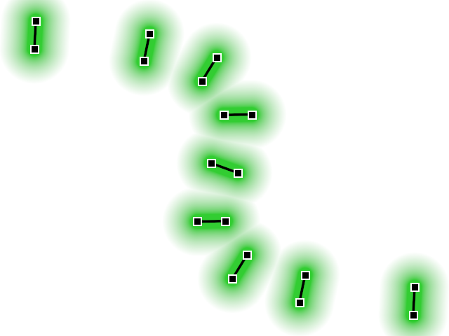
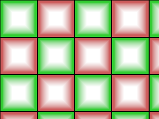
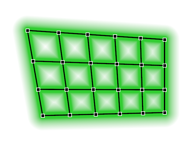
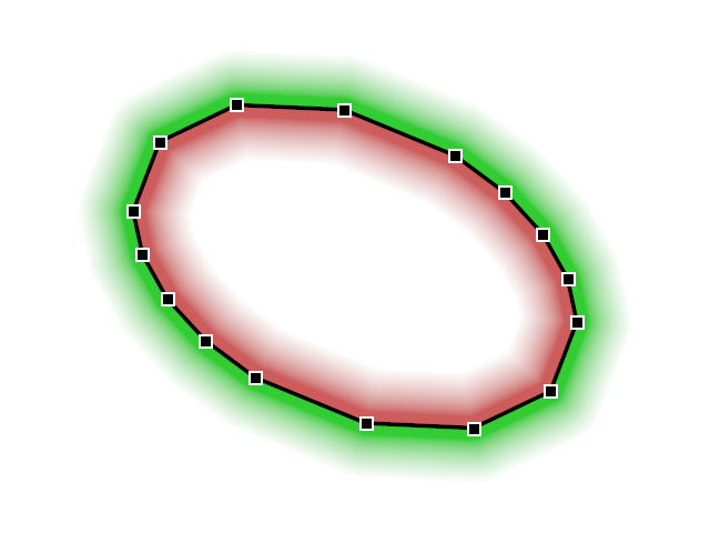
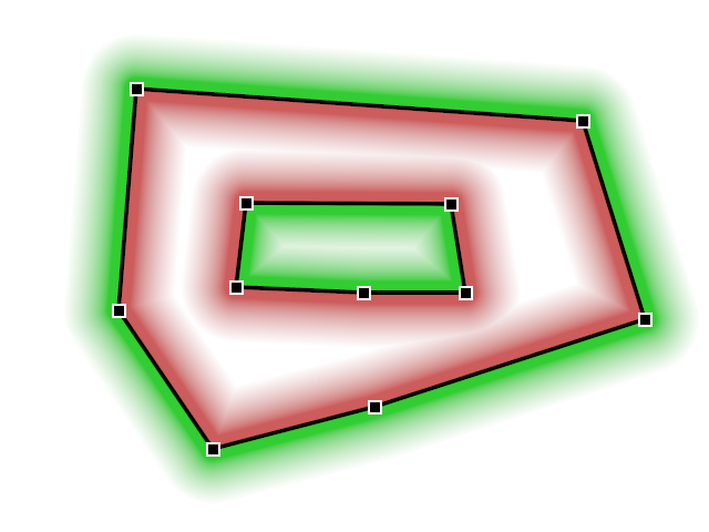
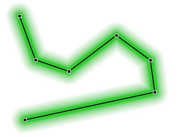
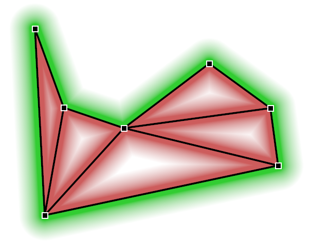
The following table shows the built-in factories for creating vector shape data. Green shades indicate the beginning of the positive part of the signed distance field (outside), the red shades indicate the beginning of the negative part (inside). Black lines indicate where the distance field is near zero. The small boxes represent shape vertices.
|
|
|
|
|
|
Shape.Curve for polyline |
Shape.Curve for polygon |
Shape.Curve for points |
Shape.Curve for line segments |
|
|
|
|
|
|
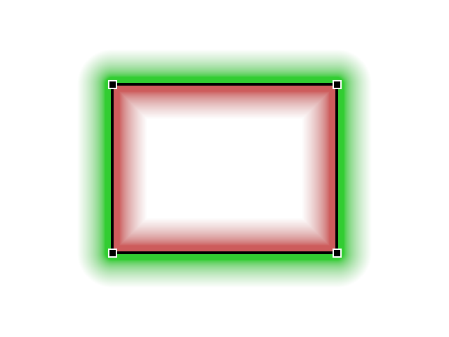
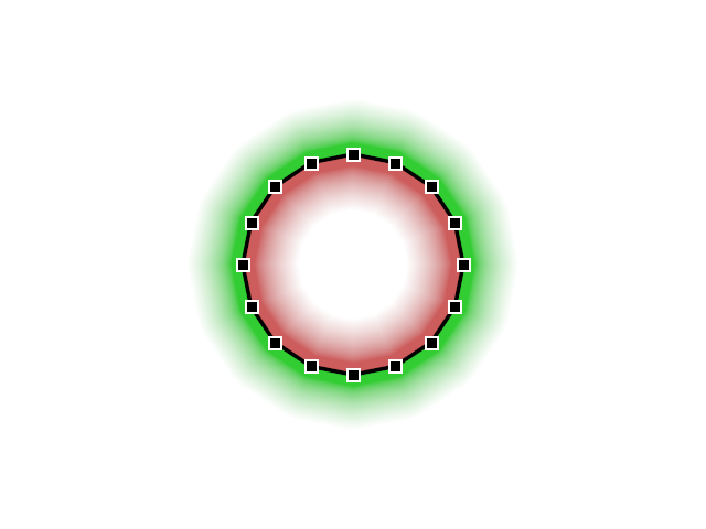
The following factories can be used to construct composite vector shapes.
|
|
|
|
|
|||
|
|||


Model Geometry
Within a scene, 3D content is represented with IModel objects. The default implementation Model may be used to construct hierarchical 3D models.
Model geometry is represented with IModelGeometry objects. The ModelGeometryBuilder class can be used to build IModelGeometry objects. Alternatively, a built-in model geometry factory may be used.
For additional information, please refer to Software Architecture / 3D Models and Geodata Processing / Model Data.
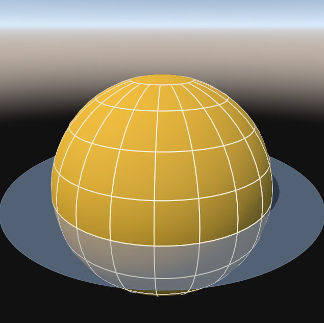
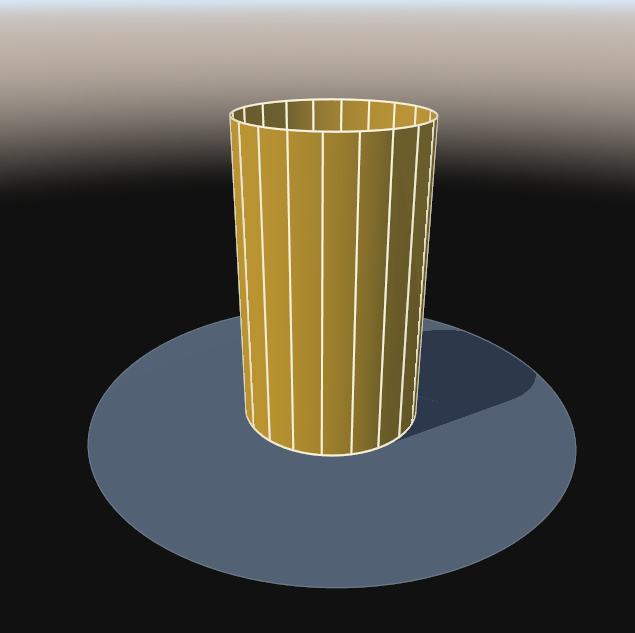
|
|
|
|
|
|
|
|
|
|
|
|
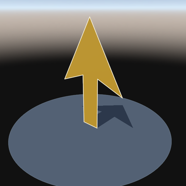

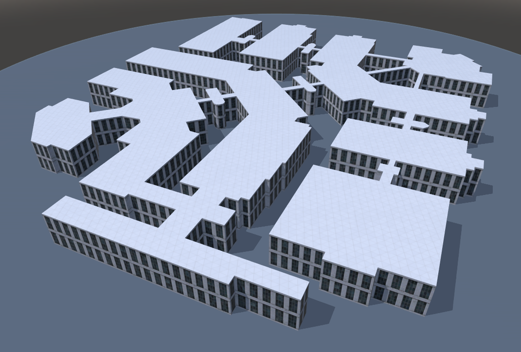
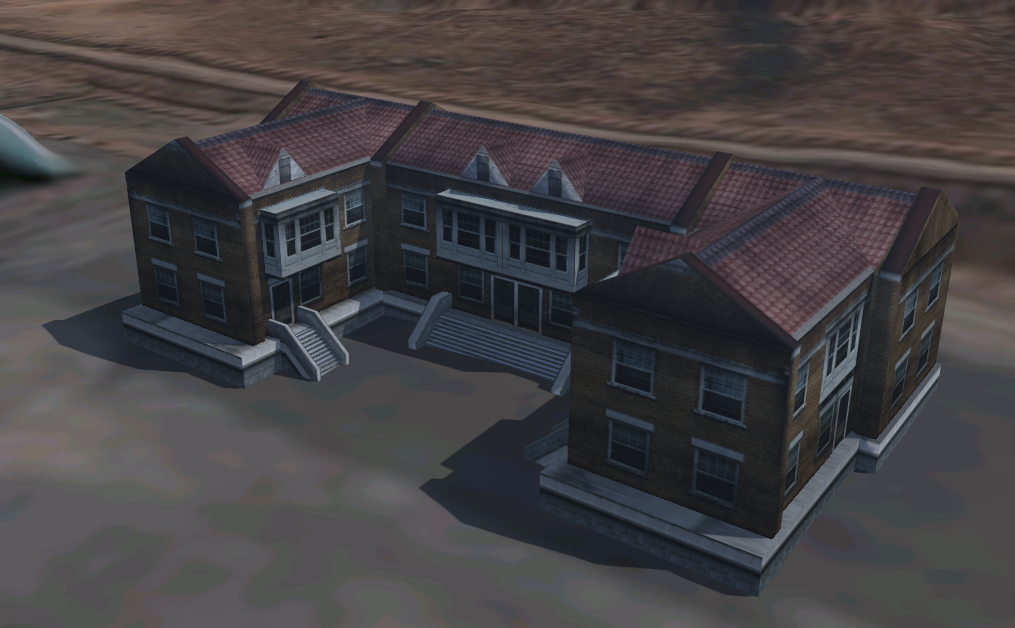
The ShapeExtruder can create textured 3D models from 2D vector data, for example to generate buildings.
|
Geo Paths
A geo path is a sequence of geo-referenced samples, each holding a number of user-definable values, including a timestamp. Smooth interpolation with C2 continuity is performed, using the sample values as control points for the underlying non-uniform B-splines.
Common geo path sample values are geographic latitude and longitude, height, yaw, pitch and roll. These are pre-defined ones, others may be defined by client code, for example the ground-speed of an aircraft.
It is common for geo path sample values to have a special numeric behaviour, which will be taken into account by interpolation. For example, longitude will wrap-around at +/- 180° and latitude will clamp to +/- 90°.
Create a geo path
Before creating a geo path, the value type for representing geo path samples must be chosen. For standard use-cases, one of the built-in ones may be used. For special cases, client-code may implement custom geo path sample types.
-
GeoPathSample
A geo path sample that contains all pre-defined values. This sample type is well-suited for aircraft flight paths. -
GroundPathSample
A geo path sample with height values relative to the terrain. This sample type is well-suited for ground tracks of vehicles. -
Example_GeoPathSample
An example for a geo path sample with a custom value.
To obtain a new geo path, create an instance of the GeoPath class, passing the chosen sample type as generic parameter. At this point, a sample type trait must also be passed as a generic parameter. The type trait provides the semantic and functionality which the GeoPath class requires. These are the type traits for the built-in sample types:
Once the GeoPath object has been created, it should be referenced through the IGeoPath interface. Doing so will hide the type trait, which would otherwise need to be specified in declarations. Also, the IGeoPathBase interface may be used, which allows access to all geo path features that do not depend on the actual geo path sample type.
Populate a geo path
After creation, a geo path is empty. Samples may be appended with ICollector.Add and IGeoPath.AddAll. Since samples are plain value types, there is no sophisticated logic involved when creating them.
Depending on the numeric behaviour of a geo path sample value (see GeoPathFlag), transformations might be necessary on the sample that is being added, before storing its values internally. Likewise, before returning interpolated sample values, the inverse transformations must be performed. This is handled transparently by the GeoPath class, according to the semantic defined by IGeoPathSampleTrait.
There are no methods for removing samples from a geo path, for example something like IVector.RemoveRange. If a sample would be removed, all subsequent ones would need to be re-computed, to make sure that the numeric behaviour is applied correctly. Instead, samples may be removed by building a new geo path, while omitting the samples to remove. For this, the IGeoPath.New method may be used as a helper.
The IGeoPathReader interface and its implementations provide some import functionality that may be used to read geo path sample values, for example from CSV files.
Use a geo path
To put a geo path into a scene, the GeoPathTrack and GeoPathTrail scene objects can be used.
On a lower level, the GeoPathTessellator class may be used to generate view-dependent 3D model geometry for a geo path.
To convert geo paths between different sample types and/or geodetic datums, the IGeoPathConverter interface may be used. Conversion between different geo path sample types can be performed with the IGeoPathSampleConverter interface.
Component Catalogue
The following sections provide an overview of the scene objects that are built into the Tinman 3D SDK as ready-to-use components.
| You can implement your own scene entities and views. Just implement the ISceneEntity or ISceneEntityView interface, preferably by subclassing one of the provided base classes. |
Terrain Objects
To add terrain objects of the High-level Terrain API to a scene, the ITerrainEntityContainer interface may be used.
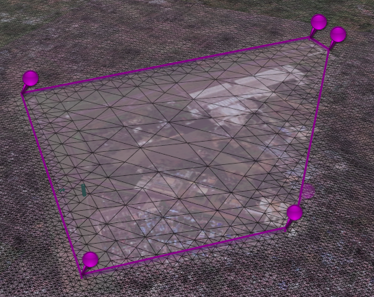
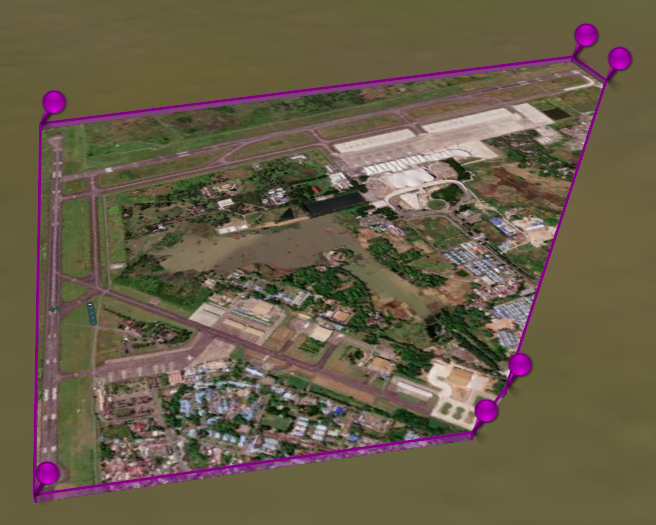
Places a texture decal onto the terrain surface, by mapping each texture corner to a point on the terrain surface.
Alternatively, the ImageDecal or TextureDecal scene entity may be used to place a texture decal.
Terrain Manipulation
This section lists scene objects that may be used to manipulate the terrain.
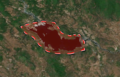
This scene entity puts a geo-referenced raster image on the terrain surface, as a static decal.
This scene entity levels elevation values in the given region by setting them to an average value.
This scene entity adds a texture layer to the terrain, sourced from pyramid data.
This scene entity puts a texture onto the terrain surface, as a dynamic decal. The decal position and transformation may be changed freely at runtime.
Scene Content
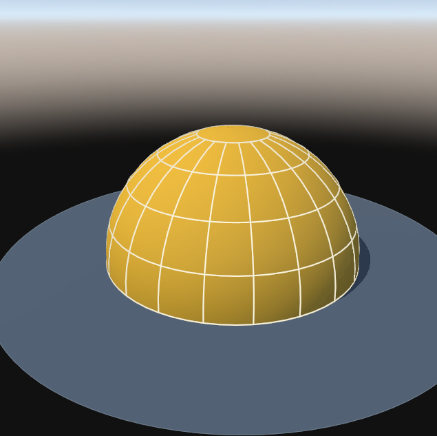
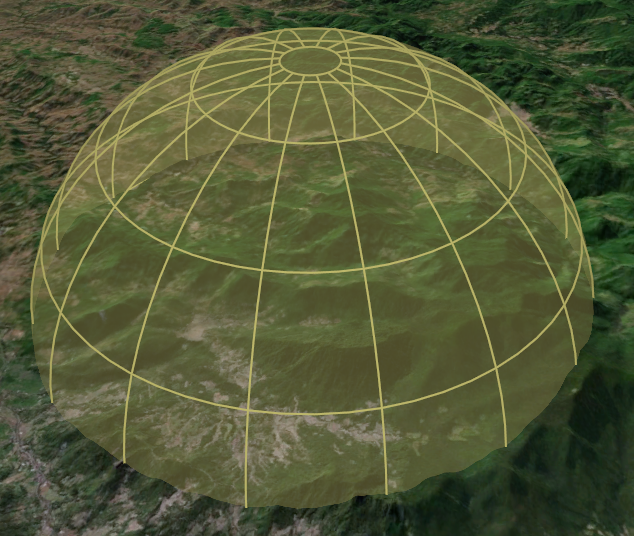
Dome / FloatingLabel / GeoPathTrack / GeoPathTrail / Vehicle
This section lists scene objects that may be used to populate the scene with content.
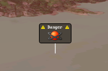
This scene entity attaches a 2D billboard screen label to a 3D location in the scene.
This scene entity adds a 3D model to the scene that represents the track of a geo-path.
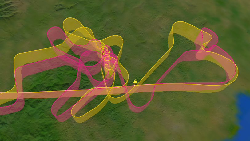
This scene entity adds a 3D model to the scene which follows the trail of a geo-path in a given time interval.
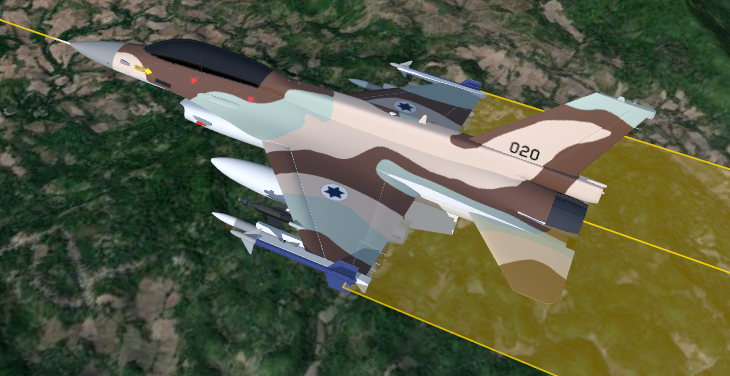
This scene entity adds a moving object to the scene and optionally attaches it to a geo path. The object may be a ground vehicle or an aircraft.
View Cameras
This section lists scene objects that may be used for camera control.
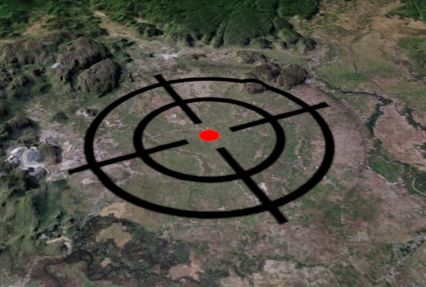
CameraFocus
This scene entity focuses zero more cameras onto some points of interest. Focussing may be performed by moving the cameras back and forth, by adjusting the camera zoom or both.
CameraFree
This scene entity view allows the user to control a camera freely by using drag & drop and 6-DOF controls.
CameraLookAt
This scene entity view makes a camera look at a specific 3D location.
CameraOrbit
This scene entity view allows the user to control a camera by orbiting around a fixed anchor point.
View Visuals
This section lists scene objects that may be used to add visuals to the scene view.
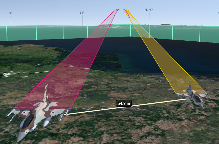
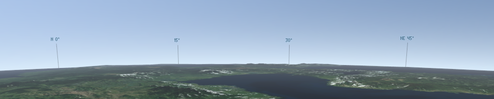
This scene entity view adds compass ticks at the horizon of the 3D view.
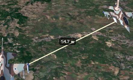
This scene entity view renders a connecting line between two 3D locations, displaying the metric distance between them.
This scene entity view puts a screen label as a 2D overlay onto the scene view.

Miscellaneous
This sections list ancillary scene objects that do not fit into any of the above categories.
Animation
This scene entity runs zero or more aggregated time-based animations in the scene, using an optional time offset and time lapse.
SceneEntity
This is the default scene entity class. Instances may be used to group other scene and terrain entities. It may be subclasses to create aggregated scene entities.